P&ID Accuracy:
An Owner’s Responsibility
Failure to document PSI ranks as #5 of the top ten violations reported by OSHA. Here we explore requirements, common errors and compliance recommendations.
by the team at GGS
April 15, 2020
Piping and instrumentation diagrams (P&IDs) are a map of your refrigeration process, and P&ID accuracy plays an important role in PSM / RMP compliance.
P&IDs are a set of schematic illustrations of the system components including mechanical equipment, piping, instrumentation and control devices showing the functional relationship and interconnection of the system.
There are no set standards defining what information P&IDs should include, however, most engineering companies that produce P&IDs agree that they should include at least the following:
- Instrumentation and designations
- Mechanical equipment with names and numbers
- All valves and their identifications
- Process piping, sizes, and identification
- Vents, drains, special fittings, and reducers
- Flow directions
- Interconnections references
P&IDs are originally drawn up at the design stage. During the design stage, the diagram also provides the basis for the development of system control schemes, allowing for further safety and operational investigations, such as a hazard and operability study (HAZOP). To do this, it is critical to demonstrate the physical sequence of equipment and systems, as well as how these systems connect.
P&IDs also play a significant role in the maintenance and changes to the process after initial build. Modifications are usually red-penned onto the diagrams until a formal revision is made defining the current plant design. They are also vital in enabling the development of:
- Control and shutdown schemes
- Start-up sequences
- Operational understanding
- Safety and regulatory requirements
P&IDs contribute to the Process Safety Information (PSI). Supporting documentation for the P&IDs include:
- Process Flow Drawings (PFDs)
- Piping Material Specifications (PMS)
- Equipment and Instrumentation Specifications (EIS)
- Functional Requirement Specification (FRS)
Refrigeration facilities that process 10,000+ lbs. of ammonia for operations must accurately maintain (P&IDs) for their system to comply with Process Safety Management as defined by OSHA.
Process safety information must include information on the hazards of the highly hazardous chemicals used or produced by the process, information on the technology of the process, and information on the equipment in the process. […].
Information on the equipment in the process must include the following: […] Piping and instrument diagrams (P&IDs).[…]
At least every five years after the completion of the initial process hazard analysis, the process hazard analysis must be updated and revalidated by a team meeting the standard’s requirements to ensure that the hazard analysis is consistent with the current process. Employers must keep on file and make available to OSHA, on request, process hazard analyses and updates or revalidation for each process covered by PSM, as well as the documented resolution of recommendations, for the life of the process.1
Failure to document process safety information, which includes P&ID’s as ‘information pertaining to the equipment of the process’, ranks as #5 of the top Ten violations reported by OSHA.
P&ID Ownership and the Consequences of Inaccuracy
P&IDs are often drafted and/or supported by a company’s mechanical contractor or system engineer. However, the responsibility (and the consequences of not meeting expectations) to keep precise documentation is on the owner of the system – not the contractor. Owners that are non-compliant are assigned some hefty fines for violations.
OSHA gives their auditors discretionary liberties related to assigning fines, though they can and do cite these violations per 1910.119(d)(3)(i)(B).
OSHA Act of 1970 / SEC. 17. Penalties (b) Any employer who has received a citation for a violation of the requirements of section 5 of this Act, of any standard, rule, or order promulgated pursuant to section 6 [Section 6 – Occupational Safety and Health Standards] of this Act, or of regulations prescribed pursuant to this Act, and such violation is specifically determined not to be of a serious nature, may be assessed a civil penalty of up to $7,000 for each violation.2
The industry has seen varying exceptions and leniencies from auditors related to these citations; though in most cases, violations are documented and fined.
A meat processing facility that closed its doors in Madison, Wisconsin, and moved to Chicago a couple years ago, was fined for inaccurate P&IDs as a result of an OSHA audit. The auditor ascribed a $21,000 fine for errors found throughout 3 of their P&ID pages – equating to a $7,000 fine per page. He justified the ‘reduced’ fine to the Plant Manager explaining that instead of imposing the mandated $7,000 per mistake (the 3 pages contained a total of 16 items in discrepancy), he fined them per page.
Results from an audit of a processing facility in Waco, TX, January 11, 2017 yielded … “a serious violation of subsection (d)(3)(i)(B) of §1910.119 for failing to ensure its piping and instrument diagrams were accurate and represented equipment that was existing and was part of the process, with a proposed penalty of $12,675.00”.3
Requirements and Common Errors
Auditors are looking to ensure all equipment and valves are represented on the drawings, and that the equipment
labels, valve tags, valve order and orientation, and components are shown identically to the corresponding identified and tagged components in the field.
As parts are replaced and changes to the system are made, the task of updating the system diagrams can be overlooked. Additionally, human error can lead to simple mistakes when documenting design and change.
Violations range from cases where entire system additions are missing from P&IDs, to more frequently recorded cases in which components and process details are documented or labeled incorrectly in the field or on the P&ID.
Whether due to a documentation or system labeling error, or an unknown characteristic of a component, this results in a mismatch of process documentation and non-compliant P&IDs. Common examples of inaccuracies include:
- Valve tag incorrectly labeled; tag numbers are reversed, on the wrong line or missing
- Directional flow marker incorrectly labeled; arrows are pointing in the wrong direction, facing each other or pointing in opposite directions on the same line
- Incorrect line type and/or line size
There are also errors in documentation that may not be matched against visible labeling in the field, but we know are likely incorrect due to process functions of the system. For example:
- A P&ID shows a strainer that was copied and pasted to the wrong position on the line – after the valve it is meant to protect.
- A line size changes from 2” to 3” with no sign of a reducer on the P&ID. Does the line in the system actually reduce in size and the reducer is missing on the P&ID, or is the line size in the system actually 2” only, or 3” only?
- Line size on the P&ID increases in size further away from the engine room. Based on mass flow rates and efficiency we generally know that moving away from the engine room, the line size would decrease, not increase. Mis-labeled P&ID or design flaw?
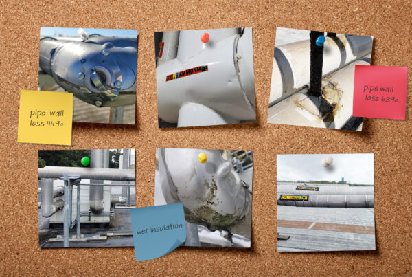
Accuracy is critical. It not only ensures protection from related violations but is also extremely necessary for first responders in the event of a release, and it supports system maintenance and code compliance justification.
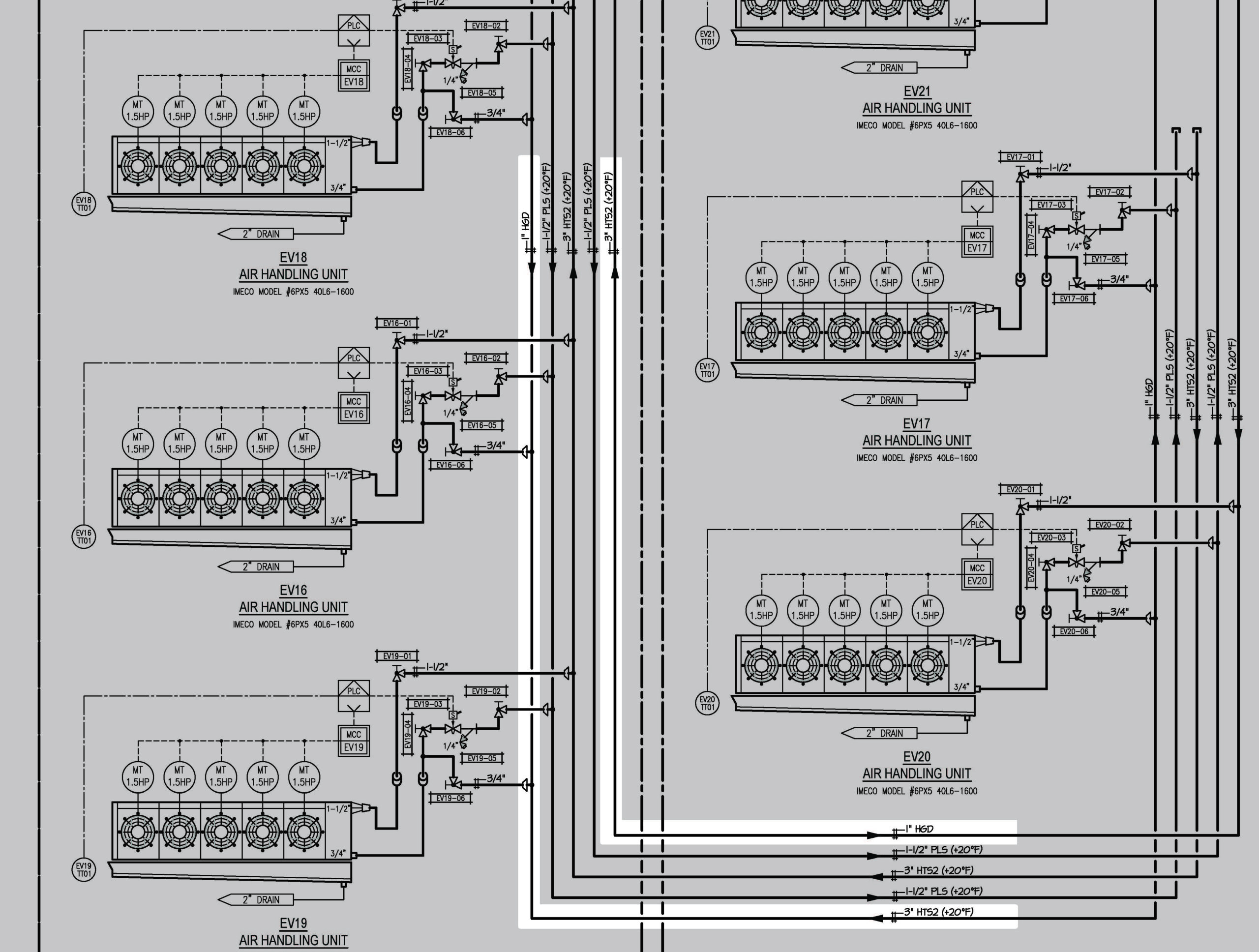
In the P&ID example here, line type, size and flow direction are incorrect on 2 separate lines. While this is likely due to a simple transposition error in drafting, it is subject to a violation.
Next Steps
Rather than assume the accuracy of your P&IDs (and system components, labeling and markers) – accept that mistakes happen. Analyze your diagrams. Walk the system and ensure:
- All components and equipment are documented on the P&IDs
- All components and equipment details are:
(a) Labeled correctly in the system, and
(b) Match the P&IDs - Nameplates for all compressors, heat exchangers, pressure vessels, and pressure-relief valves are present and legible.
- The National Board number on U-1A forms for pressure vessels matches the NB number on the vessel.
- Details such as flow direction and component location and characteristics (such as line size) on the P&ID are sensible and support the process fundamentals
- When in doubt, test. With much of your refrigeration system concealed under insulation, some details will be difficult to confirm by sight. Testing can help identify pipe size, pipe schedule, check valves, reducers and more.