
Non-Destructive Testing - NDT Methods

Choosing the right NDT method protects your system and your bottom line.

NDT technology and standardization have advanced.

Depending on your approach, you may be wasting resources, exposing yourself to hidden risks, and missing opportunities to save costs and improve efficiency.

The right method can boost efficiency, cut costs, and strengthen reliability. But not all NDT approaches deliver equally—equipment and service limitations often leave gaps. And in an era of tightened compliance requirements, you need to be strategic. That’s why examining today’s proven options is critical for you, your contractor, or consultant to make informed decisions based on efficiency, effectiveness, and scope.

Although hundreds of NDT techniques exist, industry practice has refined them to a handful of widely used methods. The following comparison highlights these relevant options, giving you the clarity you need to choose with confidence.

Key differences to consider across common non-destructive testing methods.

Non-Destructive Testing (NDT) is essential for piping systems to ensure compliance and uncover hidden risks before they become costly problems.

Ability to access everything you need tested

Piping degrades as it relates to its function, temp, contents, coating, insulation, etc. – not because of where it is located in the system. Be sure piping that isn’t being tested in your system is for good reason, not because the technology isn’t capable of testing it based on piping size, location or configuration.

Slide the scroll bar  left to right

NDT method 1 is capable of testing all piping in the image; NDT method 2 cannot access nested piping. This inaccessible piping will not get tested, leaving the health of a vast amount of piping in this system ‘unknown’.

Speed and efficiency

Each NDT method has different application requirements and thus the time it takes to test each individual location on piping ranges from a few minutes to twenty. This impacts the number of locations tested in your system in a given day, which affects cost and the thoroughness of testing.

Slide the scroll bar  left to right

NDT method 1 is capable of testing the marked locations in one half-day; while NDT method 2 is capable of testing the marked locations in a full day.

Ability to determine the condition of piping

Conditions of piping are often concealed, either because of insulation or the condition exists inside the pipe. Technologies that are unable to find and provide important metrics for early detection and preventative measures for maintenance result in incomplete testing and can jeopardize safety and compliance.

Slide the scroll bar  left to right

NDT method 1 is capable of detecting these conditions on insulated and uninsulated piping at tested locations; while NDT method 2 is capable of detecting only these conditions on uninsulated piping or where insulation has been removed at tested locations.

Common non-destructive testing methods.

General information about non-destructive testing methods commonly applied on in-service process piping and vessels, click on any method to learn more.

Comparison of key capabilities across non-destructive testing methods

One NDT is not like the other. Examining the Non-Destructive Testing (NDT) options for ammonia refrigeration pipe testing will ensure you and/or your mechanical contractor are able to select the best technology for your needs.

Print the NDT Method Comparison

Capable Capable with Exception Not capable

Radiometric Profiling (RP) Ultrasonic Thickness (UTT) Long-Range Ultrasonic Thickness (LRUT) Industrial Radiography (RT) Real-Time Radiography (RTR) Pulsed Eddy Current (PEC)
Zero holes in piping insulation Jacketing and insulation remains intact Requires holes / removal of insulation, and surface prep Jacketing and insulation must be removed for collar, not for remaining pipe tested Jacketing and insulation remain intact Jacketing and insulation remains intact Removal of insulation above 8” thick is required
Zero radiation exposure risk Testing can occur without operations interruption Testing can occur without operations interruption Testing can occur without operations interruption Radiation field present, may require test area barricades and operations interruption Radiation field present, may require test area barricades and operations interruption Testing can occur without operations interruption
All piping can be tested Can test all piping up to 24” diameter, including elbows, tees, and nested and suspended piping Can test all piping including nested and suspended Only long runs can be tested, piping must be 4″ diameter Piping must be 6”< diameter; nested, suspended, and elbows cannot be tested Piping must be 2-24″ diameter; nested, suspended, and elbows cannot be tested Piping must be <6″ diameter; suitable for magnetic steels only
Examine entire pipe profile Measures entire circumference of pipe, top and bottom, wall to wall Measures only where transducer is in contact with pipe (about 1” on a single side) Captures data on entire circumference of pipe Captures image of 1 or 2 walls Captures image of 1 wall; a full circumference profile requires 4 scans Measures average single wall
Fast evaluation Average rate is 150+ test locations per day Average rate is 50 test locations per day Average rate is 2-5 300’pipe runs per day Average rate is 30 test locations per day Average rate is 30 test locations per day Average rate is 100 test locations per day
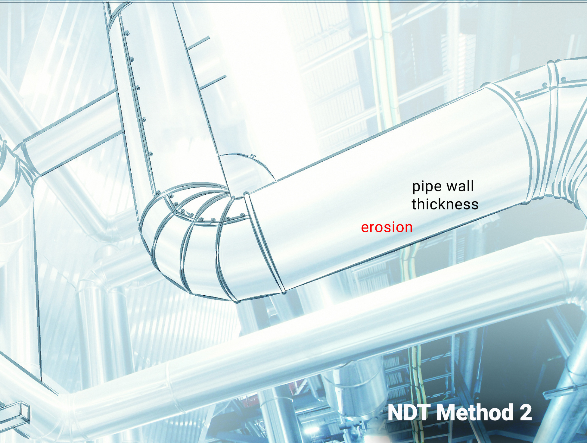
Pipe wall thickness Measured on bare and insulated piping Estimated results; prone to erroneous results on pitted or frozen pipe Does not measure thickness; flags changes in metal loss, corrosion, cracks, and welds Accuracy sensitive to film/source orientation Does not measure thickness; flags changes in metal loss, corrosion, cracks, and welds Erroneous results if isolated pitting is present
Water or ice in insulation Detected and measured (volume) Detected with visual after insulation removed Cannot detect or measure moisture in insulation Evidence may or may not be detected Evidence may or may not be detected Cannot detect or measure moisture in insulation
Corrosion Evidence is identified on bare and insulated piping Detected with visual after removed Flags changes in metal loss Accuracy sensitive to film/source orientation Flags changes in metal loss Erroneous results if isolated pitting is present
Erosion Evidence is identified on bare and insulated piping Estimated results; prone to erroneous results on pitted or frozen pipe Flags changes in metal loss Accuracy sensitive to film/source orientation Flags changes in metal loss Erroneous results if isolated pitting is present

This is why we use Radiometric Profiling to test your piping.

Our straightforward process provides you
a single, complete cost of service with no surprises.

Get a quick quote for NDT at your site.

Let's work together

“I wanted to express my gratitude for the excellent service provided by your two technicians during their recent visit. They were amazing and worked tirelessly to scan as much of the ammonia piping as possible. I had the opportunity to closely collaborate with them throughout the project, and I must say, their dedication and professionalism were truly impressive.

Engineering and Maintenance Manager
Food Distribution Facility


“The GGS team has been a valuable resource on the data needed to justify the costly expenses on addressing piping and insulation findings throughout my regions. For those of you who have piping and insulation breakdown at your sites, their data will tell the story you need to get actions on these issues. ”

Regional Manager
National Cold Storage Company


“It was great to listen to GGS explain not just the technique that we had done at our facility, but all the other different ways they can check piping as well. And the customer support they give after the scanning has been done is outstanding. They are a really good company.”

Maintenance Manager
Food and Beverage Production Facility